Planning Algorithms for autonomous robots
Path Planning for Rigid Robot – DIJKSTRA ALGORITHM
In this project I have implemented the Dijkstra Algorithm to plan the path for a robot from a given start and goal location in an environment filled with obstacles. Though the Dijkstra algorithm gives us the shortest path, it’s comparatively slower than the other advanced algorithms as the exploration space is only based on “cost to come” heuristic. In the next post, I will be sharing my experience in implementing the A* algorithm and what makes it better than the Dijkstra algorithm.
- White color – Obstacle space
- Grey color – Augmented obstacle space based on robot radius and needed clearance
- Black color – Unexplored map
- Blue color – Explored Map region
- Red color – Start and goal location chosen manually by clicking on the map
- Green color – Final shortest path for the robot to take
Path Planning for a Non-holonomic Differential Drive Robot – A* Algorithm
In this project, I have implemented the A* Algorithm to plan the path for a Non-holonomic Turtlebot3 robot with differential drive, from a given start and goal location in an environment filled with obstacles. When compared to the Dijkstra algorithm, both (the cost to come) and (the cost to go) heuristics are considered. That way, the exploration space becomes considerably small and accounts for faster goal convergence.
An 8 connected action was used for the exploration of the map. The action space is as follows,
[0,8] , [0, 10], [8, 10], [10, 8], [10, 0], [8, 0], [8, 8], [10, 10]
These are the different RPMs to the left and right wheels of the robot.
- Start point – Bottom left corner
- Goal point – Top left corner
- Blue color – Exploration based on different action set Circles and Squares – Obstacles
- Red color – Final shortest path between the start and goal coordinates
Path Planning for a Rigid Robot on a Holonomic Robot – A* Algorithm
In this project I have implemented the A* Algorithm to plan the path for a robot from a given start and goal location in an environment filled with obstacles. When compared to the Dijkstra algorithm, both (the cost to come) and (the cost to go) heuristics are considered. That way, the exploration space becomes considerably small and accounts for faster goal convergence.
- Blue color – exploration space in the map
- Black color – Unexplored free space in the map
- White color – Obstacle space
- Grey color – Augmented obstacle space to account for the robot radius + needed clearance
- Green color – Start and goal location
- Red color – Final shortest path between the start and goal coordinates
Implementation of A* Algorithm & Simulation on a Turtlebot3 using ROS and Gazebo
In this project, I have implemented the A* Algorithm to plan the path for a non-holonomic differential drive robot in ROS – Gazebo to plan a path from a given start and goal location in an environment filled with obstacles. When compared to the Dijkstra algorithm, both (the cost to come) and (the cost to go) heuristics are considered. That way, the exploration space becomes considerably small and accounts for faster goal convergence.
An 8 connected action was used for the exploration of the map. The action space is as follows,
[5, 5], [5, 7], [0, 5], [ 5, 0], [7, 0], [0, 7], [7, 7], [7, 5]
These are the different rpm to the left and right wheels of the robot.
- Start and Goal Point – green color
- Final path – red color
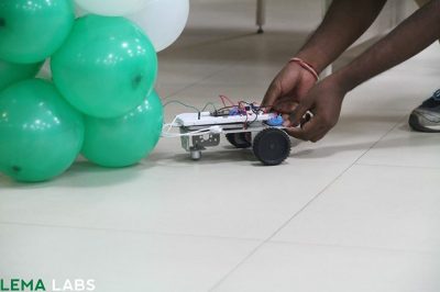
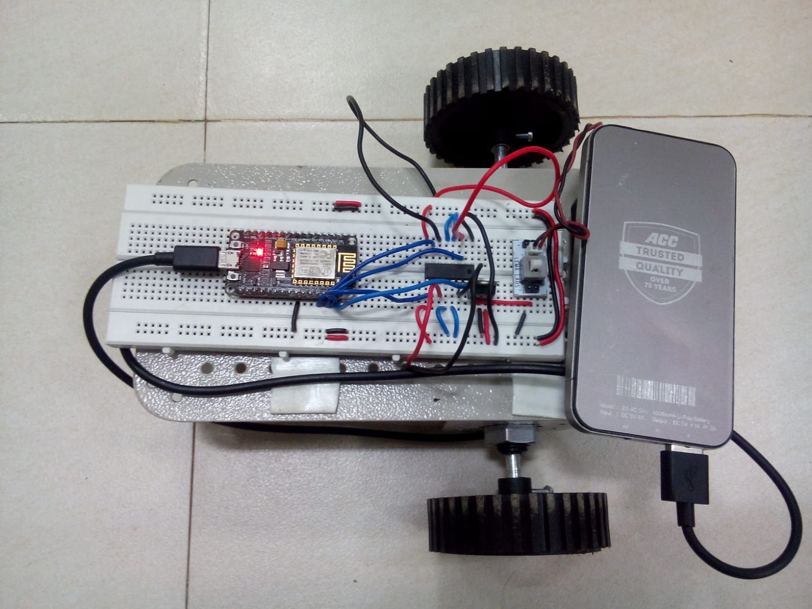
RSSI Based Path Planning for Robots
(Aug 2016 – Sep 2016)
- An android mobile phone (with mobile hotspot turned on) was used as the source of the signal which was designated as the goal.
- Devised an algorithm to track the mobile’s location using the RSSI signal strength.
- Node mcu micro-controller with inbuilt ESP8266 Wi-Fi module was used for the robot to track the Dbm values from the Mobile’s Wi-Fi.
- This robot was programmed to detect the location of the Wi-Fi signal it has been locked on to. The robot approaches the direction in which the Wi-Fi signals (RSSI – Received Signal Strength) increases. A Nodemcu module with inbuilt ESP8266 wifi module was used on the robot.